This page explains how to build your very own power monitor, connect it to the internet and send the data to a webservice.
Note: this guide was designed to work with American power meters, your mileage may vary elsewhere.
No soldering is required, but a bit of electronics experience is helpful.
For the impatient, you can skip to the schematic.
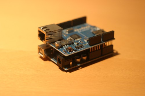
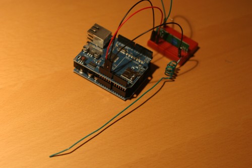
First snap the ethernet shield to the arduino.
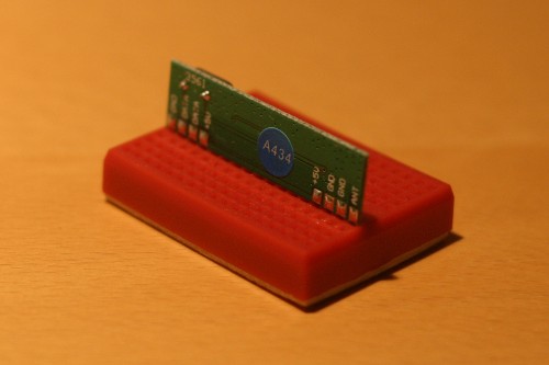
Next push the wireless receiver into the breadboard. You'll have to use a
little bit of force to get it in.
Be careful not to bend any pins.
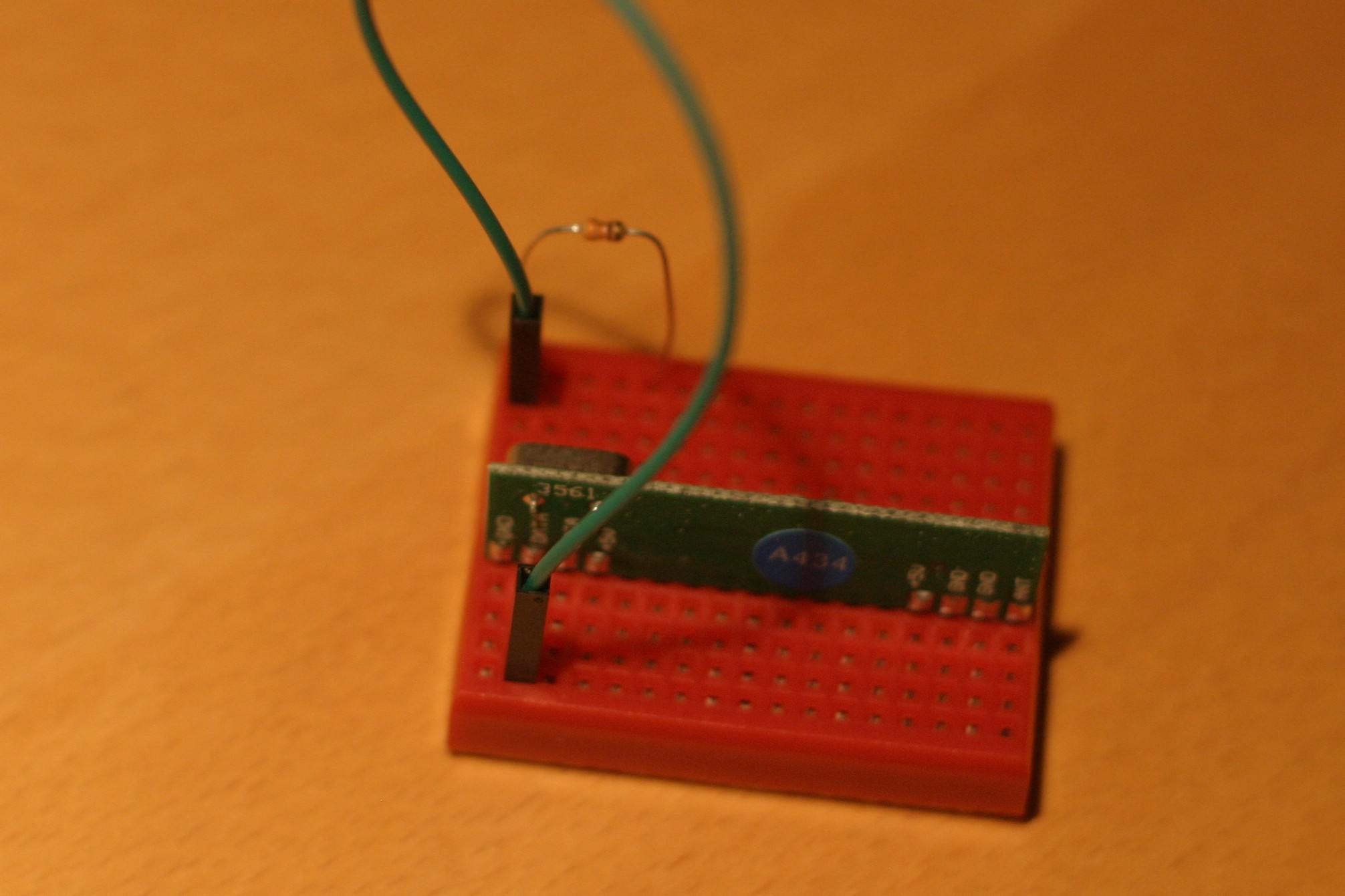
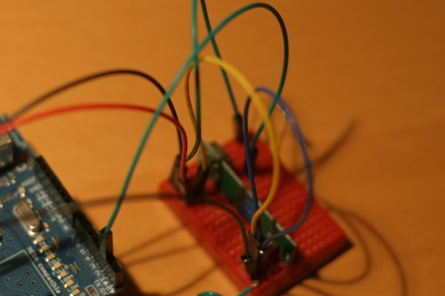
Place the 990 Ω resistor on the opposite side of the bread board. Now
connect the leftmost data pin from the receiver to the resistor.
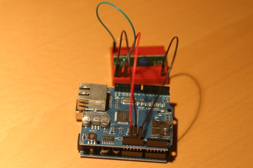
Now connect the 5V pin on the ethernet shield to the receiver's leftmost
5V pin. Next connect the first ground pin on the ethernet shield to the leftmost
ground pin on the receiver and connect the other arduino ground pin to the
rightmost ground pin on the reciever. While redundant, these
connections are used to improve the reception of the receiver.
Create an antenna by taking a length of 34cm of the 24 gauge wire. Strip
one end of it. Wrap the stripped end around a pencil 6 times and then
leave the rest straight. Note: This is more of an art than science,
don't worry about being too exact here.
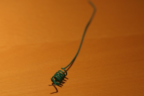
Connect the antenna to the antenna pin.
Now connect the 2 leftmost ground pins on
the receiver together. Then connect the two rightmost 5V pins on the receiver
together.
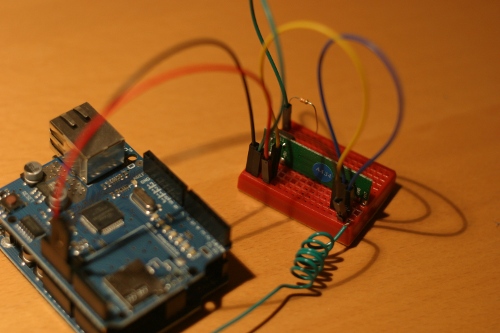
Connect the other side of the resistor, from the third step, to pin 2 on
the ethernet shield (shown here as the green wire)
Now you've completed the hardware necessary to read signals from the Black & Decker power monitor. The next step is to create an HTTP server that will gather the data that is collected from the arduino that you just built. I've made a very basic example based in Ruby that contains my best understanding of the Black & Decker protocol in server. The server needs to be available on port 80 at an address which is accessible to the network that the arduino will connect to.
Now that you have your data collection server you'll need to get the firmware going on the arduino. Download the modified EthernetDHCP and EthernetDNS arduino libraries and extract them into your arduino library directory (~/arduino/libraries/).
Download the flash library to the same location.
Then download the Firmware and extract it into you Arduino directory (~/arduino/)
Now open up your Arduino environment (it must be version 0018), open the Firmware sketch, modify API_HOSTNAME in HTTP.h to point to the server that you setup above and upload to the Arduino. Once you have successfully flashed the Arduino, make sure everything is working by opening the serial console at 115200 baud and then connecting the device to ethernet. Several messages should appear.
Now follow the instructions that came with the Black & Decker Power Meter and make sure it is functioning properly by viewing the provided display. Only after you have confirmed it is working should you proceed.
Now connect the device to an ethernet port on your router and power it on. The LED should come on once a network connection has been established. After several seconds the LED will turn off. It should then turn on briefly every 30 seconds indicating a packet has been received. If no flashes are recieved, connect it to your computer and monitor the serial console for logging messages. Otherwise you should soon see requests from the arduino on your data collection server and everything is working properly.
Happy hacking!
